so now the weather is getting better,..and now it's crap again, I thought I would do an update, as I've been working on the RS for some reason or another!
So, into the black bin bag of looms and the first one out is the interior loom. It's actually in pretty good shape with only fairly minor problems.
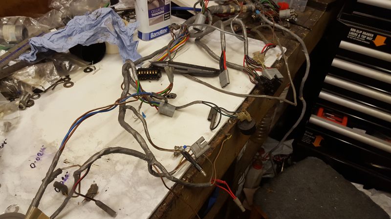
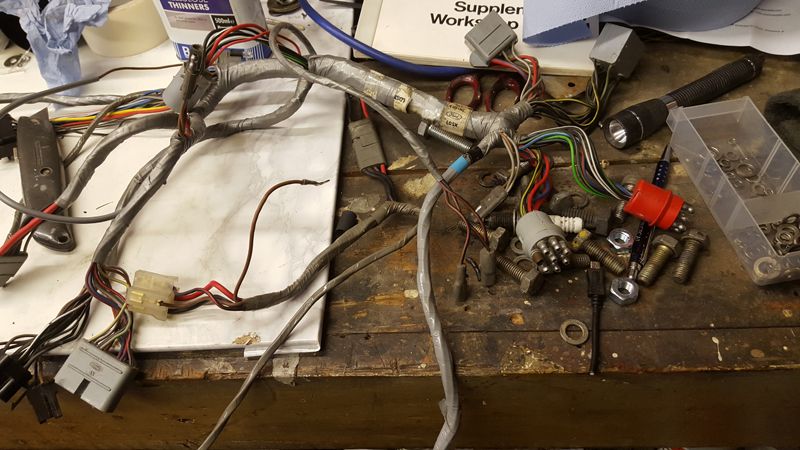
here are where tere were some scotch locks....convenient, yes, but hate them. Best solution here is to tape these up in my view
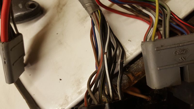
Then there were these:
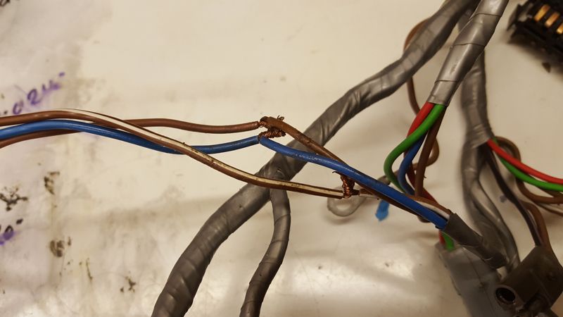
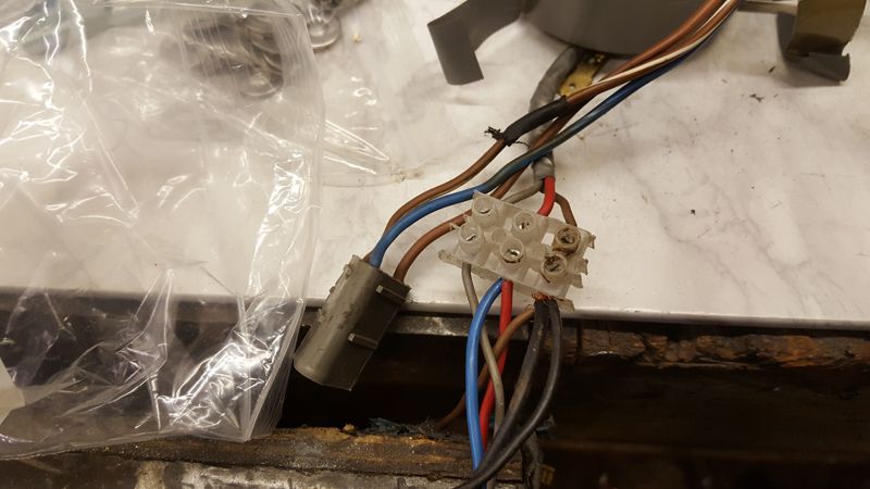
so fixed and heat shrunk and will be taped over
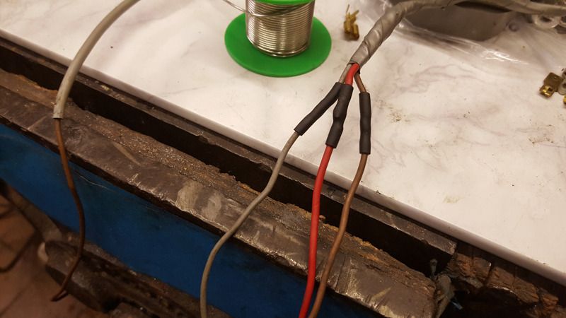
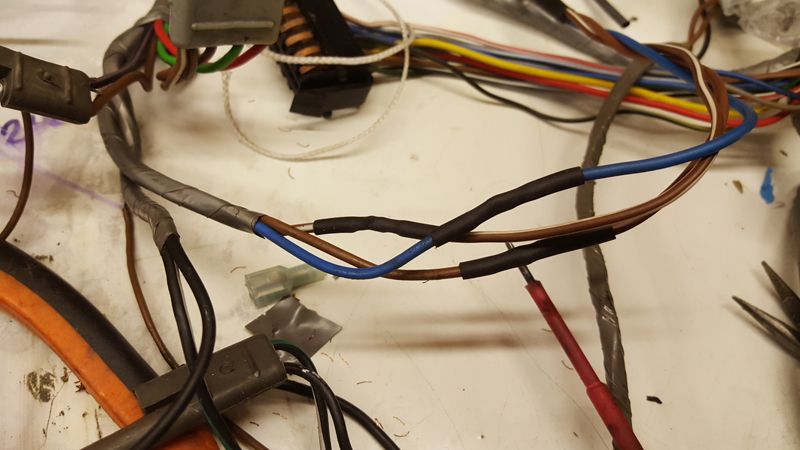
Once more fixed
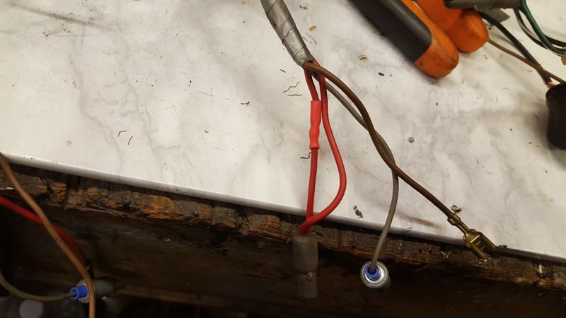
Taped over and no one will ever be the wiser....and ecen then this is all buried under the dash!
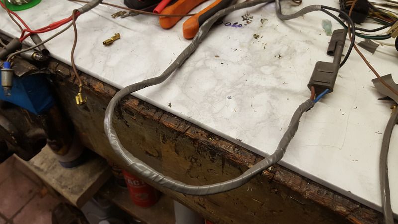
and new ends on the curtesy light switches as these were non existent!
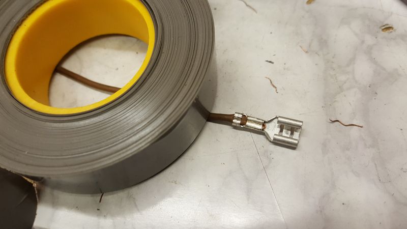
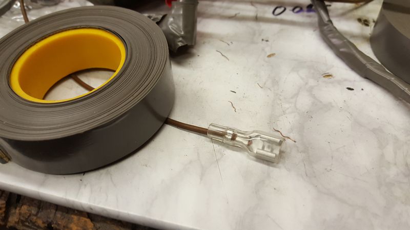
and then it's a case of starting to put it into the car!
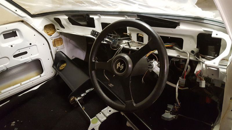
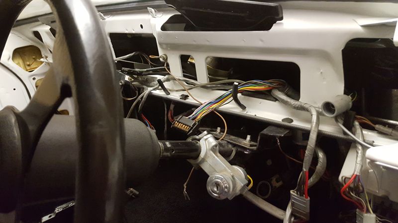
This is where taking photo's during dis assembly proved invaluable!
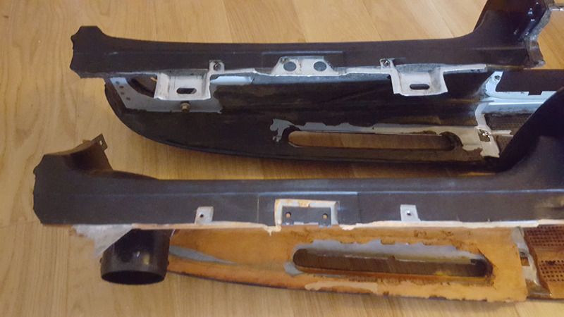
My original dash was in a fairly poor state with burns and cuts, so I sourced a black dash from a mk3 capri. Very very similar, but there are a few differences.
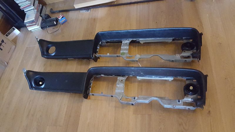
The original dash is on the bottom
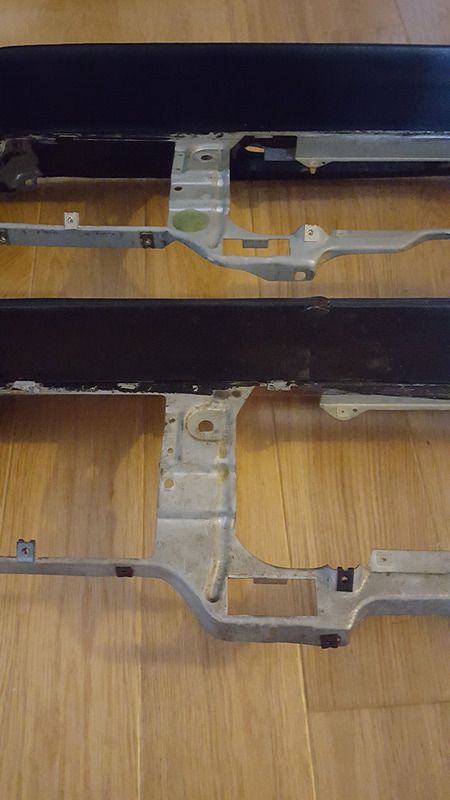
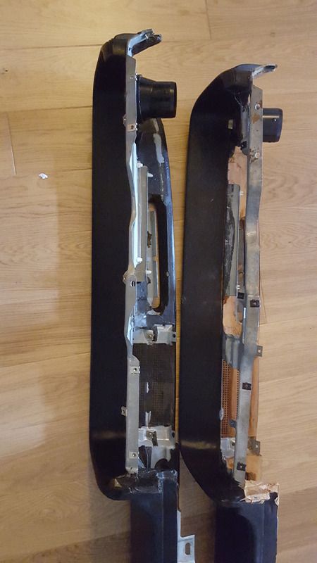
The two additional bracket/extensions stop the mk3 being fitted, so these parts are now on the garage floor
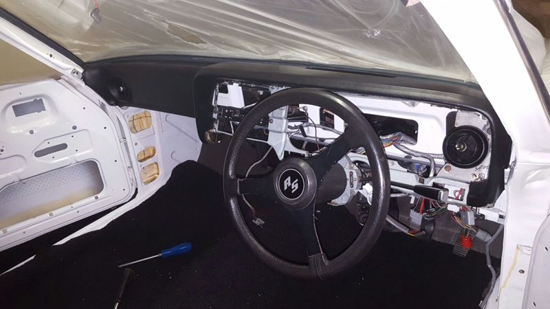
and there she is! Looking rather nice with NOS heating vents!
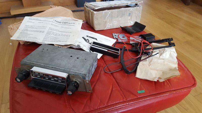
While I was on a roll, I thought I would dig out the NOS radio fitting kit and a period Ford radio I had picked up at an auto jumble.
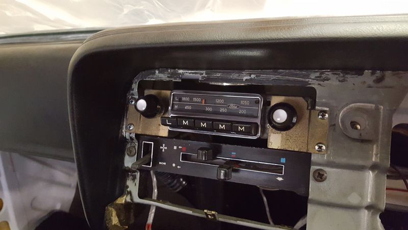
Looks rather good...no idea if it works!
The remainder of the loom was routed to the rear, through the rear panel...once again, reference photo's proved invaluable.
I then assembled the rear bumper and put a good coating of Dinitrol on the rear:
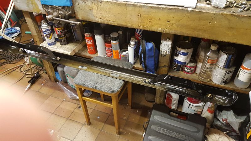
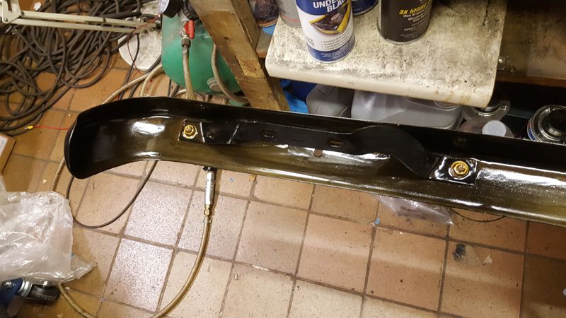
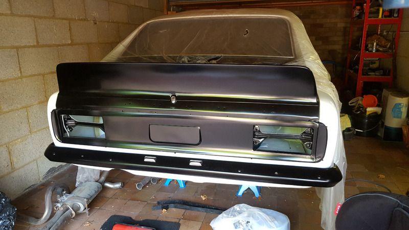
and putting it on with new number plate lights, connecting them up to the loom
Then back to the engine. After weighing up the various options, I went for a new alloy cam gear with matched steel crank gear. I've heard a few stories now of the all steel cam gears eating into the cam retainer, which would be behind this gear, as they are no machined correctly.
So now I had the gear, time to time the cam. Offset keys used to be available for the essex..I even had some...but that was 4 house moves ago! so timing them 100% accurately can be tricky, but close enough should do.
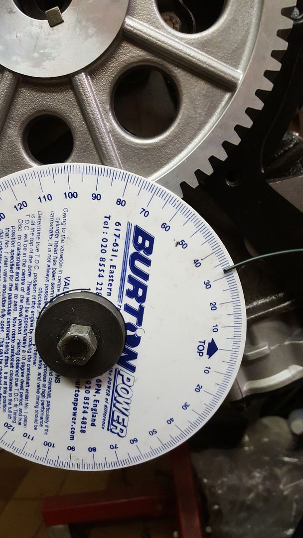
So first up, find true TDC. Here is my bodged together piston stop. The idea here is that you wind the crank one direction and it stops before TDC. Wind it back in the other direction and it stops after TDC. Using a timing wheel on the crank and a temporary pointer (I used gardening wire held under a bolt). I initially make a good guess as to where TDC is and set up my timing wheel so that my pointer indicates TDC. I then wind the crank so the piston is half way down the bore and bolt on my piston stop. Wind the crank one way, note the reading on the degree wheel, wind it the other way and once again, note the timing on the degree wheel. If I've guessed right, the reading should be the same, so x degrees before and after TDC. If they are different, move the timing wheel such that they are the same (add your readings, divide by 2 and adjust the wheel so that timing is shown when you are at the piston stop...you can then check this by rotating the crank back and forth to the piston stop each time to check your readings are the same before and after TDC)
Timing/Degree wheel in place
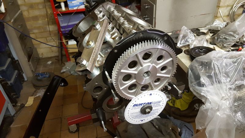
So here I have 32 degrees BTDC
and here I have 32 degrees ATDC
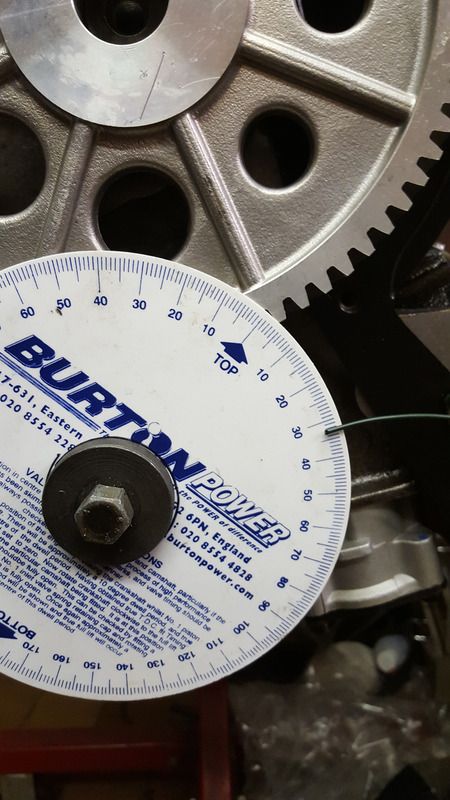
so if I take my piston stop off, I can rotate the crank to where my pointer indicates TDC and I know it will be accurate...but don't loosen the timing wheel or more the pointer from now on in!
Here is my cam card, where the details of the timing are shown.
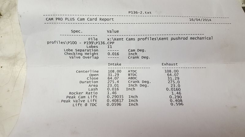
This is a custom grind provided by a good friend and engine builder. Kent Cams ground the cam, however. The number I'm interested in for timing is the inlet center line of 108 degrees ATDC. This means that when the crank is 108 degrees after TDC, the inlet on number 1 cylinder will be at the center of it's peak lift. As there is some dwell at peak lift, it's not easy to identify exactly where this is...just like identifying TDC using piston position alone. In a very similar fashion to finding TDC, I put the timing gears on as per factory, so with the dots on the crank and cam wheel aligned, this would be a good starting point to see what I got.
First thing to do is to set up a dial gauge on the inlet follower of number one cylinder. I used very thin oil as I wanted the follower to follow the cam profile closely and not 'stick' in it's before due to thick oil (this isn't an issue once valve springs are exerting pressure on the followers via the push rods).
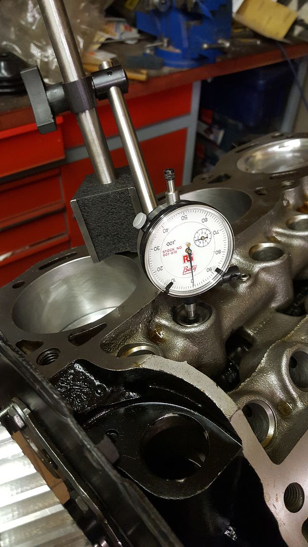
I would intially rotate the crank to where I'm getting what looks like full lift on the inlet cam. I would see the dial gauge increase, stop, then no change and then start to decrease, as the follower moves up, remains at peak lift for a while and then falls. You could actually note the reading on the degree wheel a soon as the dial gauge reaches it's peak and note it again when it starts to decrease and in theory, half way in between would be the lobe center line. You can take this a stage further by identifying this center point and setting your gauge to zero, as I did. I then moved the crank anti clock wise, well past the peak of the cam lobe and then wound it forwards, clockwise, so engine rotation, until I was 50 thousandths of an inch below zero...so 50 though below peak lift. Note the degree wheel value. Then continue rotating past peak lift, so zero on the gauge and then until the gauge read 50 below zero again, though past peak lift...and then note the degree wheel timing again. Half way between the two is your lobe center line (and this does assume the lobe profile is symmetrical) I was getting 139.5 one side and 91 degrees the other, so added uip to 220.5, divided by two means my lobe center line was at 110.25 degrees. Given I have 76 teeth on my cam gear, each tooth represents 4.7 degrees, so moving the gear one tooth gets me to about 105 degrees. The choice I had was to run the cam advanced by 3 degrees or retarded by 2 degrees. I chose advanced as in theory, this opens the inlet slightly sooner and increases low end torque as the expense of high end....but I honestly don't think there will be that much in it.
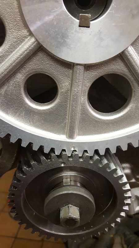
so here is where the two timing gears ended up:
so now time for the heads. Bye bye forged pistons!
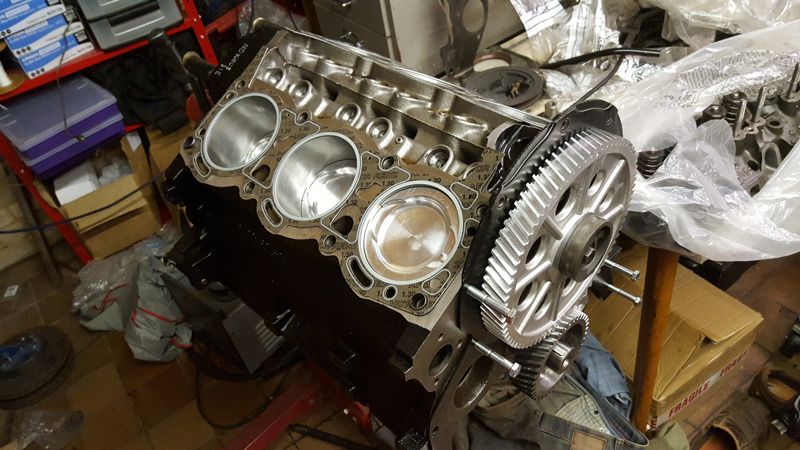
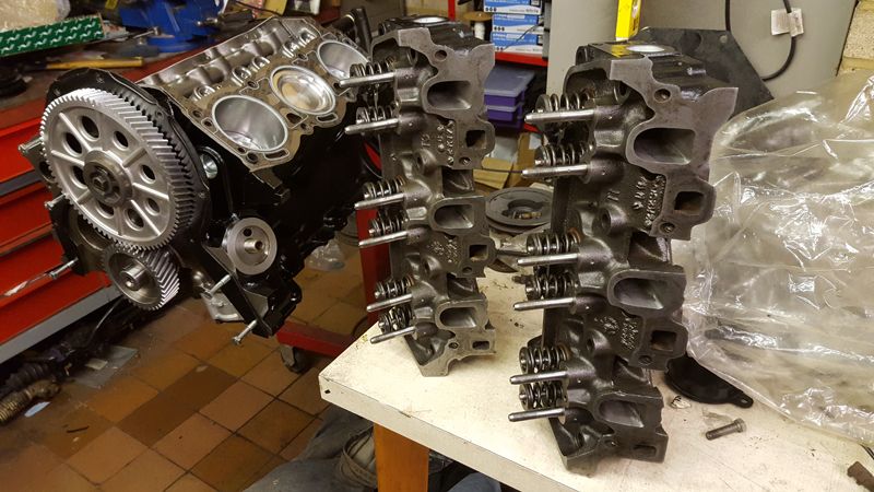
You can just see the ribbed effect on the inlet ports due to the CNC porting. For those who don't know, CNC porting is automated porting using computer controlled machines, where the porting from port to port on a head is 100% consistent, so each port should be identical, from one port to another, from one head to another, so ensure consistency.
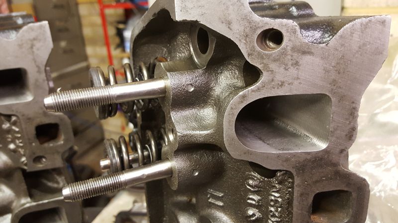
First head in place......although followers went in first, as once the heads are on, you won't get the cam followers in!
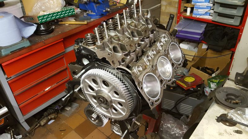
Getting there! Heads on and push rods and rockers cleaned. Oil goes rough the push rods and rockers, so it's important to make sure the oil ways in these components are clean.
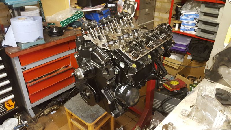
I appear to have a selection of inlet manifolds:
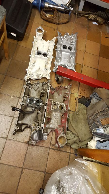
The white one came from my Mk2, the one with the remnants of red paint is allegedly and RS3100 inlet and the one with the black pipe was my original manifold on this car...and the silver one is a standard manifold.
Here you can see both my original and the red manifold look ported compared to the standard original manifold:
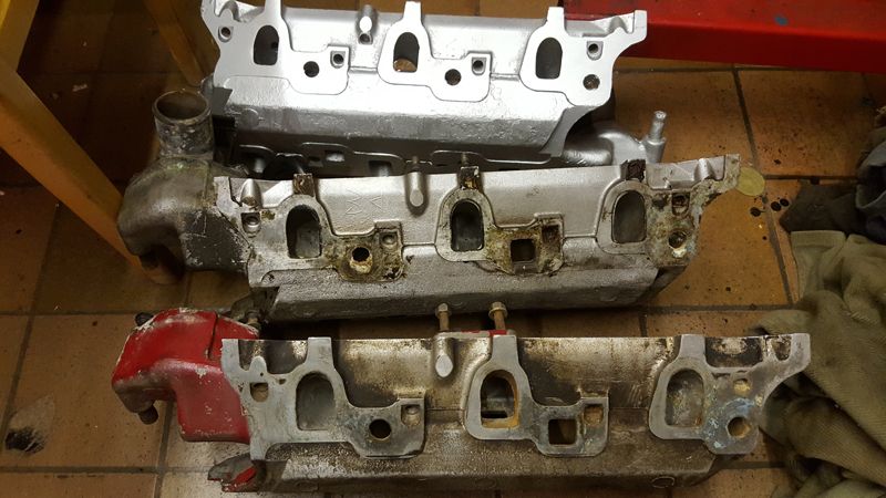
So I'm, going to see which one fits best and matches the ports in my heads. I've had issues with a modified essex manifold not fitting before and not sealing the water ways correctly, resulting in a leak.
So up to date. More as it happens!